| Tool | Purpose | |------|---------| | PicoScope 7/8 | Export waveform gallery + notes to PDF | | Snagit / Greenshot | Capture scope screenshots | | Adobe Acrobat / LibreOffice | Combine images + text | | Notepad++ / Markdown | Quick formatting for text notes |
Controls the visual height of the signal. If diagnosing a 12V actuator, a 20V scale ensures the entire signal fits on the screen without clipping.
Determines the scale of the vertical axis. Adjust this so the waveform fills most of the screen without clipping. pdf automotive oscilloscopes waveform analysis
A comprehensive PDF will display the difference between a DIS (Distributorless) system where one coil fires two plugs simultaneously (one on compression, one on exhaust). The exhaust stroke requires very low voltage. If both peaks are equal, you have a bad plug on the compression side.
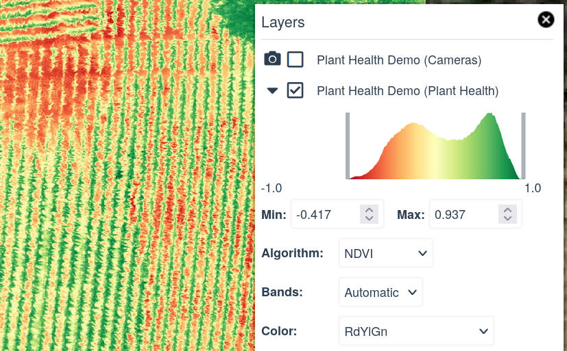
: This reference document provides expected voltage values and visual patterns for common components like Air Flow Meters (AFM), noting that idle voltage should be approximately 1.0V and rise to 4.5V under acceleration. Source : Reference Waveform Library (PDF) . Key Waveform Interpretation Principles | Tool | Purpose | |------|---------| | PicoScope
One of the most efficient ways to use an oscilloscope is comparing a "bad" signal to a "known good" one. Technicians should build a digital library (PDF or image files) of waveforms from properly functioning vehicles, categorized by manufacturer and system. 5. Summary Table of Waveform Characteristics Signal Type Key Feature to Check AC/DC Square/Sine Consistent amplitude, sync between sensors Injector Duty Cycle PWM Voltage "hump" indicating needle lift Ignition Coil High Voltage Transient Correct burn time ( MAF Sensor Frequency/Voltage Smooth, linear rise on acceleration CAN Bus Differential Digital 2.5V2.5 cap V resting, no sharp noise Conclusion
Replacing a spark plug with a pressure transducer allows you to view mechanical engine cycles in real-time. Shows true mechanical compression. Exhaust Valve Opening: Verifies physical camshaft timing. Adjust this so the waveform fills most of
The Waveform: The mechanic captured the cam and crank signals. Using the PDF’s "time ruler" technique, he measured the delay. The PDF told him the correct delay was 48ms at idle. His waveform showed 51ms.